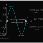
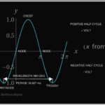
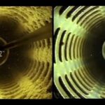
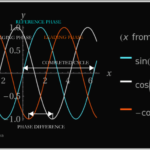
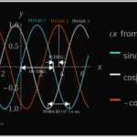
Figure 2. A simple sine wave with a period of 360° and an amplitude of 1. In single phase power the x-intercepts are 180° from each other. A full period is 360°. A single phase motor has a crest approximately every 16.5 milliseconds giving the motors a tendency to vibrate more, which may contribute to a shortened bearing life.
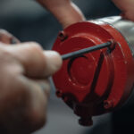
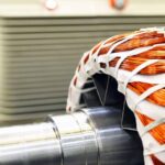
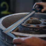
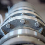
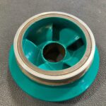
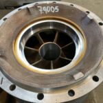
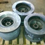
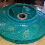
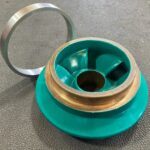
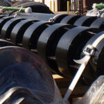
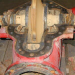
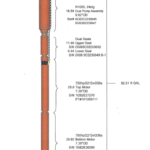
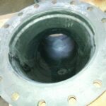
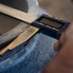
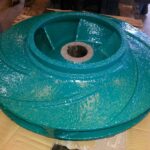
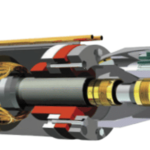
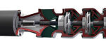
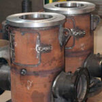
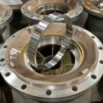
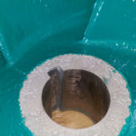
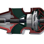
Impeller wear ring
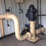
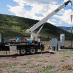
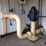
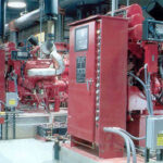
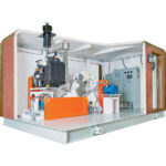
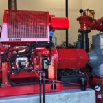
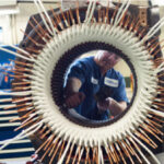
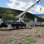
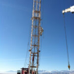
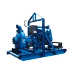
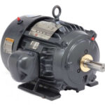
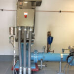
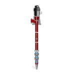
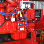
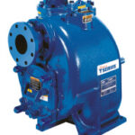
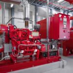
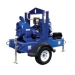
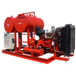
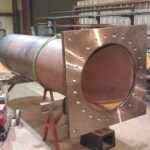
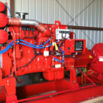
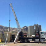
80 Series® Engine Driven
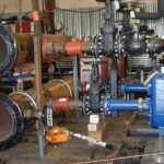
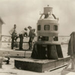
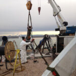
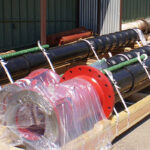
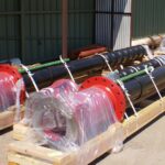
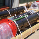
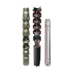
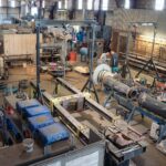
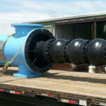
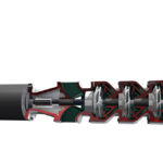
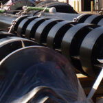
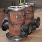
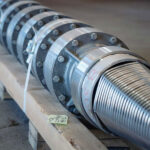
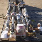
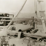
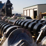
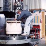
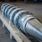
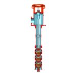
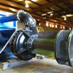
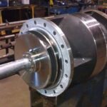
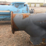
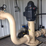
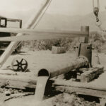
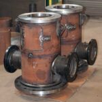
Schlumberger Pump Assembly
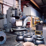
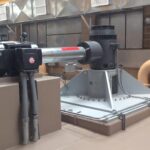
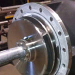
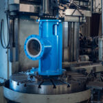
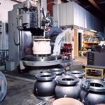
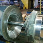
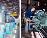
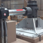
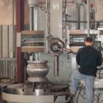
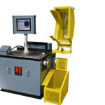
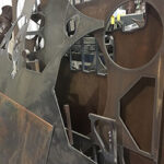
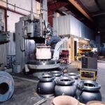
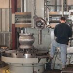
Vertical Lathe
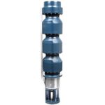
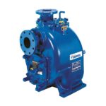
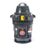
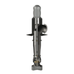
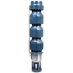
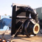
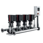
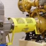
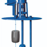
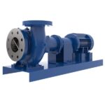
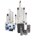
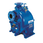
SF Series®
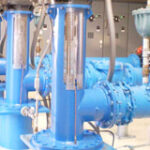
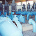
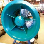
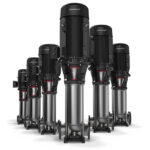
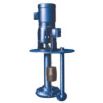
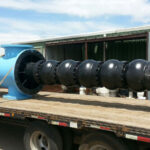
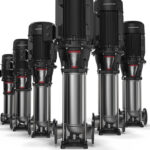
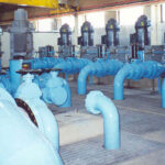
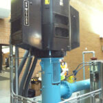
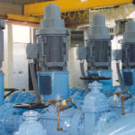
Vertical Turbine Pumps, Deep Well
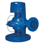
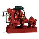
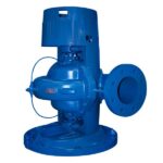
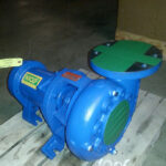
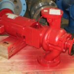
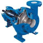
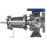
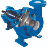
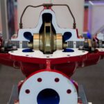
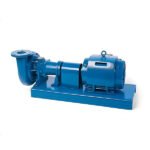
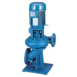
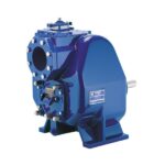
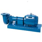
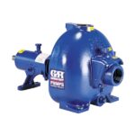
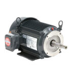
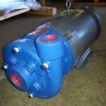
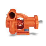
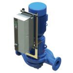
Model 342A Single Stage End Suction
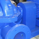
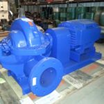
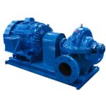
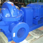
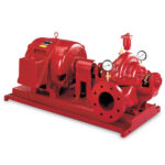
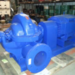
Model 411 Horizontal Split Case
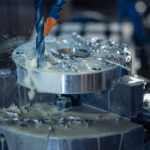
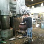
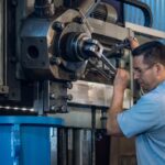
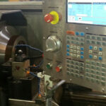
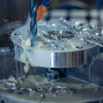
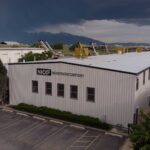
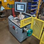
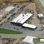
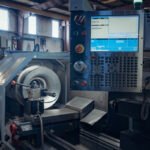
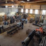
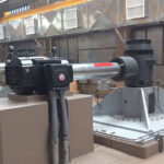
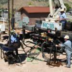
Computer Numerical Control Machine (CNC) at Nickerson
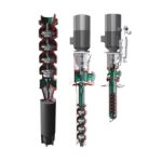
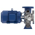
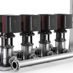
Ultra V Series® and UltraMate®
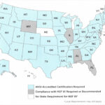
“NSF/ANSI 61.” NSF RSS. The Public Health and Safety Organization, n.d. Web. 07 June 2017.
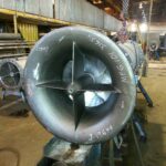
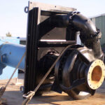
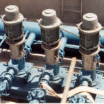
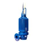
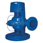
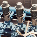
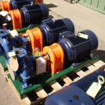
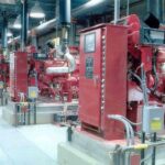
Gorman-Rupp SF Series® Submersible Solids-handling Pump
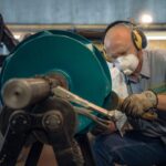
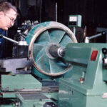
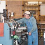
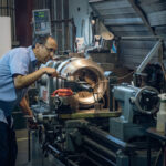
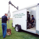
CNC machine, where computers are used to control the movement and operation of the mills, lathes, and other cutting tools.
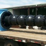
National Pump Vertical Turbine Pumps, API 610
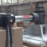
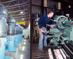
Horizontal Lathe
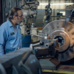
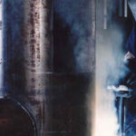
Machinist at Nickerson Company running a state-of-the-art CNC machine.
Bowl wear ring
Computer Numerical Control Machine (CNC) at Nickerson
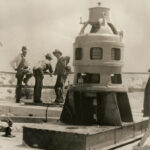
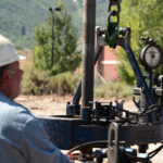
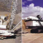
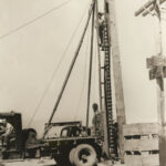
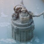
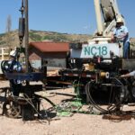
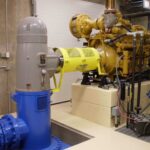
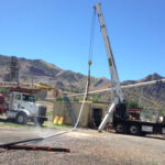
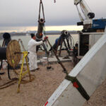
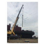
Utah Lake Cascade Pump
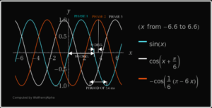
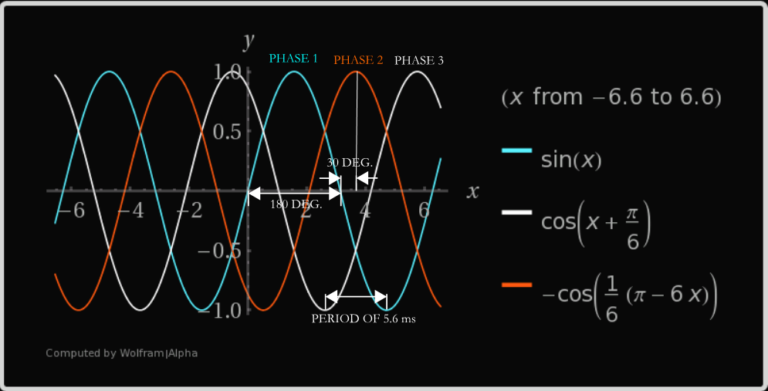
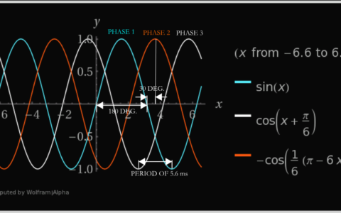
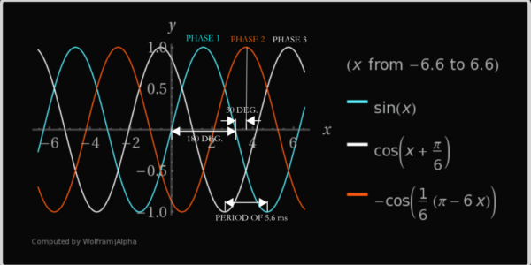
Figure 1. The general arrangement of a three phase waveform.