All centrifugal pumps contain rotating impellers within stationary casings. As a pump impeller spins, it exerts a centrifugal force on the liquid flowing through it and expels the liquid through the casing volute channel at a higher pressure. However, some of the liquid will recirculate back between the impeller and the casing running clearance, resulting in erosion, excessive clearances, and decreased efficiency. If not addressed, the growing clearances will produce a cascading effect that results in even higher flows and more erosion, which can significantly affect performance and pump life.
Properly sized and installed wear rings significantly reduce recirculation around the impeller, balance axial thrust forces, and provide protection for the more expensive and highly-engineered impeller and casing. Related to these benefits, wear rings also assist with reduced casing temperature, cavitation, vibration, and noise.
Wear Ring Location, Fit & Clearances
Wear rings may be installed on the impeller skirt, in the pump casing, or both on the impeller skirt and in the pump casing. When wear rings are installed either on the impeller or in casing but not both, the ring material is typically a softer metal, however, it can also include non-metal composites. When wear rings are installed both on the impeller and in the casing, the same material is generally used for both rings and can have significantly increased hardness and erosion resistance. Rings must have a Brinell hardness of at least 50 units of difference unless both the surfaces have a hardness of at least 400 units.1
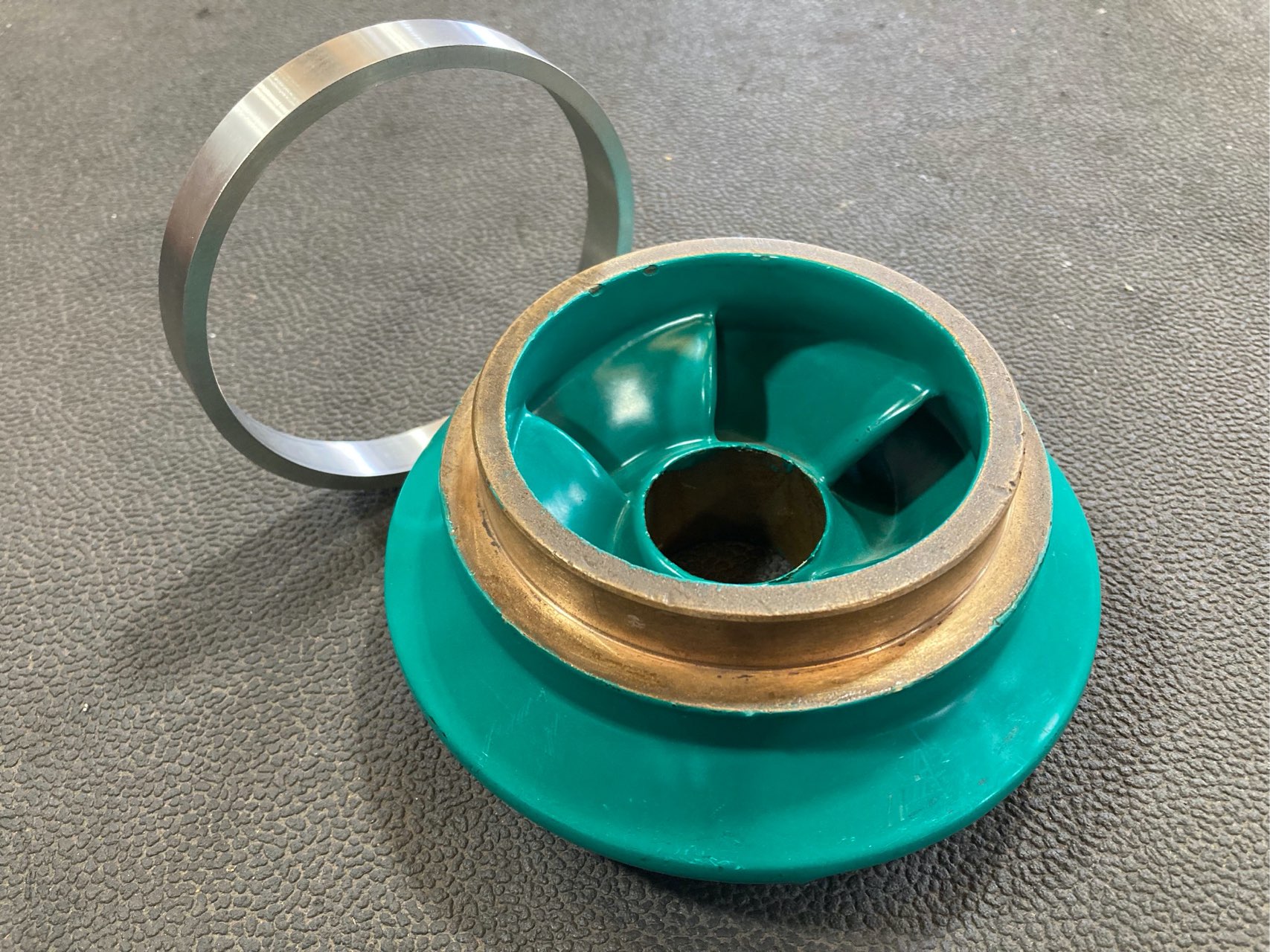
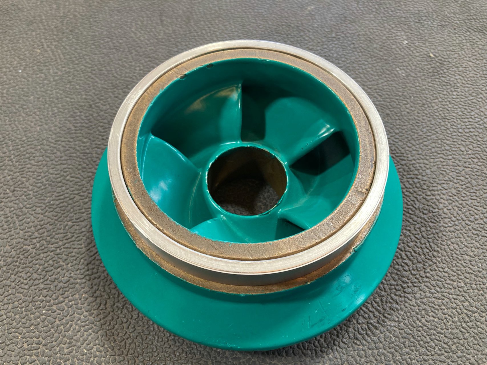
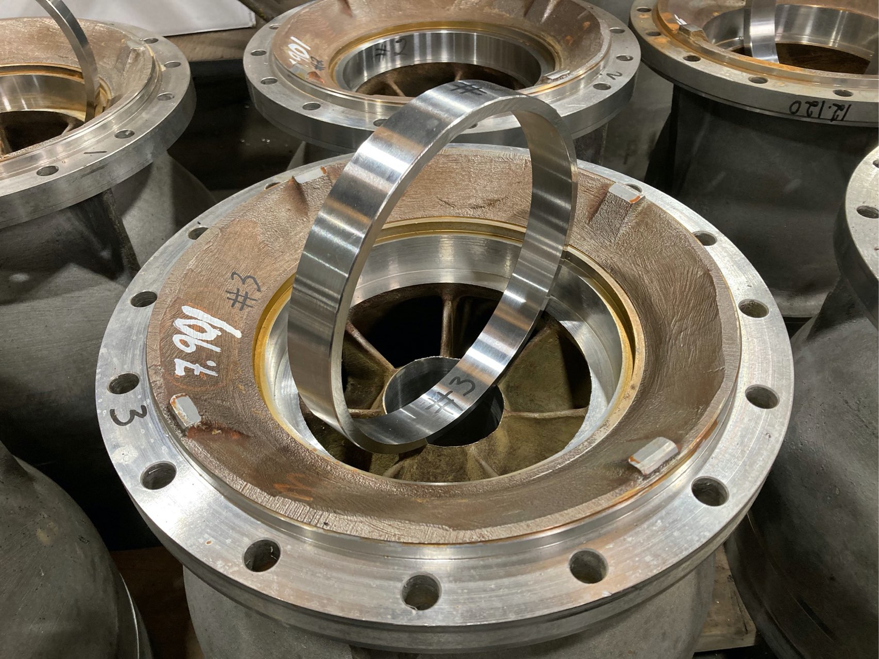
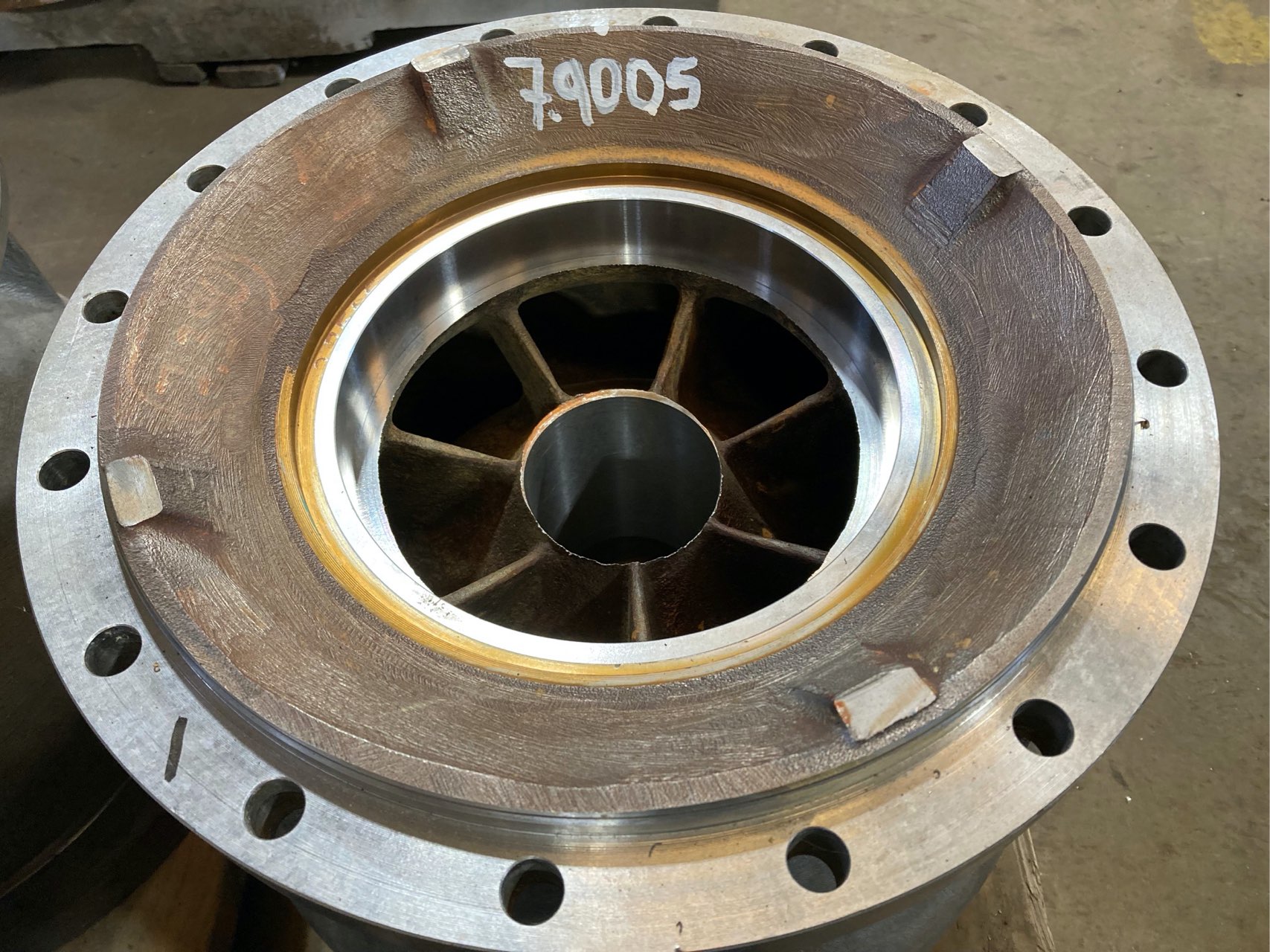
Wear rings are machined to be an exact fit to the part they are being mounted on and require special procedures to install. Wear rings must be held in place by a press fit and secured by either a locking pin, set screws, or tack welding. If a wear ring is not properly secured, there is a possibility that when the pump is operating it may shift the wear ring, leading to damage or destruction of other pump components.1
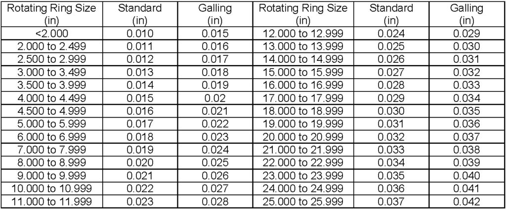
Wear ring clearances are determined by the rotating wear ring diameter and the potential for galling. As the rotating ring size increases, the recommended diametrical clearance also increases. The table below shows a set of recommended wear ring clearances from one major pump manufacturer. Similar tables can be found in most vertical turbine installation, operation, and maintenance manuals from each pump manufacturer.
Wear Ring Minimal Clearance
API 610 Wear Ring Clearance Guide
While it is always better to follow a manufacturer’s guidelines for wear ring clearances, sometimes that information may not be available. If the clearance information is not available from the manufacturer, the API 610 wear ring clearance guide below may be used instead.1
- For a wear ring with a 2” diameter or less, API lists the minimum diametral clearance as 0.010”.
- For every 0.5” increase of the impeller wear ring OD, the 0.010” diametral clearance increases by 0.001”. So, from 2.000” to 2.499” OD, the diametral minimum clearance is 0.011”.
- For impeller wear rings with OD of 5” up to 26”, every 1” increase in the impeller wear ring diameter results in an additional 0.001” of minimum diametral clearance.
Wear Ring Material Selection
It is also essential that wear ring material is selected based on the liquid being pumped. Special consideration should be taken when replacing wear rings in potable water systems. Wear rings should also have a low galvanic potential to adjacent parts, but not be a galling combination.
Installing wear rings is an economical and efficient way to restore a pump’s performance as well as protect against excessive casing temperature, cavitation, vibration, and noise. In our next post, we will review the energy costs and savings that can be attained by maintaining proper wear ring clearances.
- API Standard for Centrifugal Pumps, 12th Edition.
1 Comment
Thank you for your information. It has been of great help
I have a 200/ 250 5 stage pump I am repairing and the wear rings and impeller are bronze pb 2. Which is very expensive here in South Africa. Your article gave me an idea.